

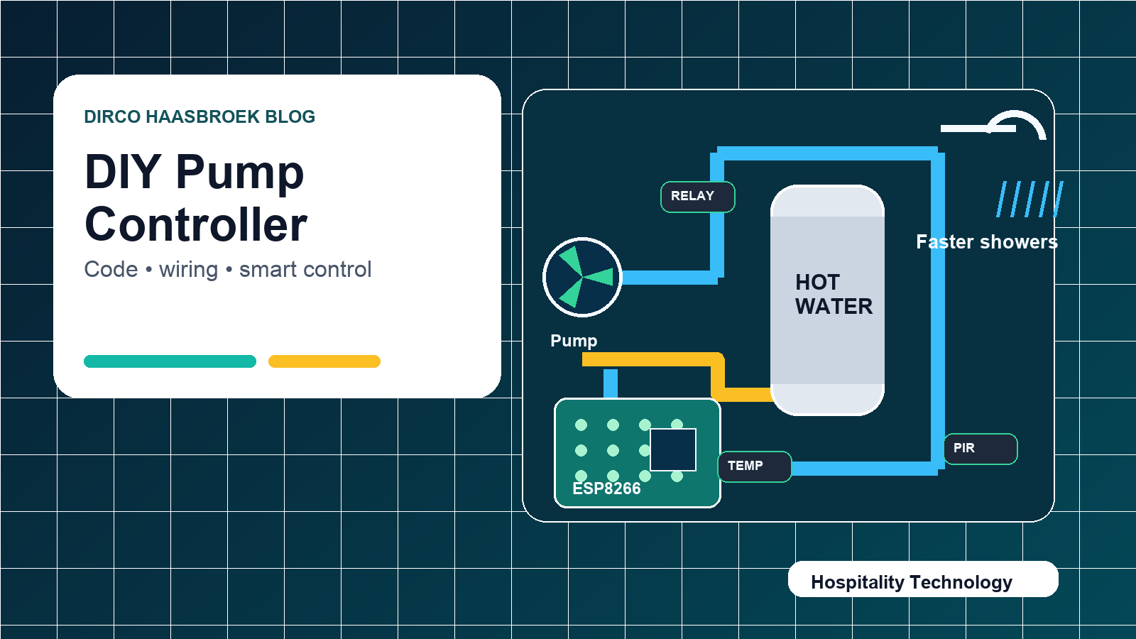
This is the technical follow-up to the hotel hot water circulation pump article. The first post explains why a controlled hot water circulation pump can be useful for hotels, guest houses, lodges, and self-catering properties. This one focuses on the practical side: controller logic, wiring, components, and starter Arduino code.
The example below uses an ESP8266 relay board, a DS18B20 waterproof temperature sensor, two PIR motion sensors, and a pressure switch to control a hot water circulation pump. It is intended as a prototype and learning reference, not a plug-and-play commercial hotel installation.
Important safety note before you start
Hot water systems and mains electricity can be dangerous. In a hotel or guest house, this type of installation should be reviewed and installed by a qualified plumber and a qualified electrician. The low-voltage control side is suitable for experimentation, but the pump, geyser, relays, fuses, isolators, earthing, enclosures, and wet-area protection must be done properly.
Project goal
- Detect when someone enters a bathroom or service area.
- Optionally detect water use with a pressure switch.
- Check the hot water pipe temperature.
- Turn the circulation pump on if the pipe is still cool.
- Stop the pump when the pipe reaches the target temperature.
- Prevent the pump from running continuously with runtime and rest-time limits.
Components used
- ESP8266 2-channel relay board
- Hot water circulation pump suitable for the plumbing system
- DS18B20 waterproof temperature sensor
- 4.7kΩ resistor for the DS18B20 data line
- Two PIR motion sensors
- Pressure switch or flow/pressure trigger input
- Suitable DC power supply for the controller
- Electrical enclosure, cable glands, protection, fusing, and isolation
Basic system logic
If motion is detected OR pressure switch is triggered:
    If the hot water pipe is below the restart temperature:
        Turn pump ON

While pump is ON:
    If pipe reaches target temperature:
        Turn pump OFF
    If maximum runtime is reached:
        Turn pump OFF
    If temperature sensor fails:
        Turn pump OFF

After pump stops:
    Wait for minimum off time before allowing another start
Recommended starter settings
- Target temperature: 40°C at the monitored pipe point.
- Restart temperature: 35°C, so the pump does not short-cycle.
- Maximum runtime: 3 minutes as a safety limit.
- Minimum off time: 2 minutes before the pump can restart.
- Sensor check delay: 1 second.
These values are only starting points. In a real property, tune them according to pipe length, pump size, pipe insulation, geyser temperature, number of rooms, and guest demand patterns.
Wiring overview
DS18B20 temperature sensor
DS18B20 red wire     → 3.3V
DS18B20 black wire   → GND
DS18B20 yellow/data  → GPIO2 / D4
4.7kΩ resistor       → between data and 3.3V
Fit the sensor securely to the hot water return pipe or monitored pipe section. Use proper thermal contact and insulation over the sensor so it reads the pipe temperature more reliably.
PIR motion sensors
PIR 1 OUT → GPIO14 / D5
PIR 2 OUT → GPIO12 / D6
PIR VCC   → correct sensor supply voltage
PIR GND   → GND
Check the PIR output voltage before connecting it to the ESP8266. ESP8266 input pins are 3.3V logic and are not 5V tolerant.
Pressure switch
Pressure switch side 1 → GPIO13 / D7
Pressure switch side 2 → GND
The example code uses the ESP8266 internal pull-up resistor, so the pressure input is active LOW. When the switch closes to ground, the controller treats it as triggered.
Pump relay
Relay COM → live input feed
Relay NO  → pump live wire
Pump neutral and earth → wired according to local electrical standards
For hotel use, do not rely only on a small hobby relay board for final protection. Use correct isolation, fusing, an enclosure, cable strain relief, and preferably a proper contactor or pump-rated switching arrangement if required by the pump load.
Arduino IDE setup
- Install the ESP8266 board package in Arduino IDE.
- Select the correct ESP8266 board for your relay module.
- Install the
OneWireandDallasTemperaturelibraries. - Connect the controller by USB.
- Upload the code.
- Open the Serial Monitor at
115200baud to watch temperature, motion, pressure, and pump status.
ESP8266 Arduino code
#include <OneWire.h>
#include <DallasTemperature.h>

// ---------------- PIN SETUP ----------------
// Change these pins if your ESP8266 relay board uses different GPIOs.

#define RELAY_PUMP_PIN      5    // GPIO5 / D1 - Relay 1 for pump
#define RELAY_SPARE_PIN     4    // GPIO4 / D2 - Relay 2 spare

#define PIR_1_PIN           14   // GPIO14 / D5
#define PIR_2_PIN           12   // GPIO12 / D6
#define PRESSURE_PIN        13   // GPIO13 / D7

#define ONE_WIRE_BUS        2    // GPIO2 / D4 - DS18B20 data pin

// ---------------- SETTINGS ----------------

#define RELAY_ACTIVE_LOW    true

float targetTemp = 40.0;          // Stop pump when pipe reaches this temp
float restartTemp = 35.0;         // Allow restart only below this temp

unsigned long maxRunTime = 180000;      // 3 minutes max pump runtime
unsigned long minOffTime = 120000;      // 2 minutes rest time after pump stops
unsigned long sensorCheckDelay = 1000;  // Check every 1 second

// ---------------- DS18B20 SETUP ----------------

OneWire oneWire(ONE_WIRE_BUS);
DallasTemperature sensors(&oneWire);

// ---------------- STATE ----------------

bool pumpRunning = false;
unsigned long pumpStartTime = 0;
unsigned long pumpStopTime = 0;
unsigned long lastSensorCheck = 0;

float currentTemp = 0;

// ---------------- RELAY FUNCTIONS ----------------

void relayWrite(int pin, bool on) {
  if (RELAY_ACTIVE_LOW) {
    digitalWrite(pin, on ? LOW : HIGH);
  } else {
    digitalWrite(pin, on ? HIGH : LOW);
  }
}

void pumpOn() {
  if (!pumpRunning) {
    relayWrite(RELAY_PUMP_PIN, true);
    pumpRunning = true;
    pumpStartTime = millis();
    Serial.println("Pump ON");
  }
}

void pumpOff() {
  if (pumpRunning) {
    relayWrite(RELAY_PUMP_PIN, false);
    pumpRunning = false;
    pumpStopTime = millis();
    Serial.println("Pump OFF");
  }
}

void setup() {
  Serial.begin(115200);
  delay(500);

  pinMode(RELAY_PUMP_PIN, OUTPUT);
  pinMode(RELAY_SPARE_PIN, OUTPUT);

  relayWrite(RELAY_PUMP_PIN, false);
  relayWrite(RELAY_SPARE_PIN, false);

  pinMode(PIR_1_PIN, INPUT);
  pinMode(PIR_2_PIN, INPUT);

  // Pressure switch wired between GPIO13 and GND
  pinMode(PRESSURE_PIN, INPUT_PULLUP);

  sensors.begin();
  Serial.println("Hot Water Circulation Pump Controller Started");
}

void loop() {
  unsigned long now = millis();

  if (now - lastSensorCheck >= sensorCheckDelay) {
    lastSensorCheck = now;

    sensors.requestTemperatures();
    currentTemp = sensors.getTempCByIndex(0);

    bool motion1 = digitalRead(PIR_1_PIN) == HIGH;
    bool motion2 = digitalRead(PIR_2_PIN) == HIGH;
    bool pressureTriggered = digitalRead(PRESSURE_PIN) == LOW;

    bool trigger = motion1 || motion2 || pressureTriggered;
    bool tempValid = currentTemp > -50 && currentTemp < 100;
    bool tempReached = tempValid && currentTemp >= targetTemp;
    bool tempCoolEnough = tempValid && currentTemp <= restartTemp;
    bool maxRuntimeReached = pumpRunning && (now - pumpStartTime >= maxRunTime);
    bool minOffPassed = !pumpRunning && (now - pumpStopTime >= minOffTime);

    Serial.print("Temp: "); Serial.print(currentTemp);
    Serial.print(" C | Motion1: "); Serial.print(motion1);
    Serial.print(" | Motion2: "); Serial.print(motion2);
    Serial.print(" | Pressure: "); Serial.print(pressureTriggered);
    Serial.print(" | Pump: "); Serial.println(pumpRunning ? "ON" : "OFF");

    if (pumpRunning) {
      if (tempReached || maxRuntimeReached || !tempValid) pumpOff();
    } else {
      if (trigger && tempCoolEnough && minOffPassed) pumpOn();
    }
  }
}
Implementation notes for hotels and guest houses
- Start with measurement: time how long each room takes to receive hot water before deciding where to install sensors or pumps.
- Insulate pipes first: a circulation pump on uninsulated pipework can waste energy.
- Avoid continuous operation: use temperature, timer, or demand triggers to reduce runtime.
- Use safe defaults: the pump should fail off if the temperature sensor fails or reads outside a believable range.
- Document the install: future maintenance staff need a simple diagram, settings, and controller notes.
- Think about Legionella safety: do not lower water storage temperatures or modify circulation strategy without professional advice.
Testing checklist
- Confirm the relay starts in the OFF state after power-up.
- Confirm the DS18B20 reports a realistic temperature.
- Trigger each PIR sensor and confirm the Serial Monitor changes.
- Trigger the pressure switch and confirm it reads correctly.
- Test that the pump stops at the target temperature.
- Test that the maximum runtime stops the pump even if the pipe does not heat up.
- Test that the minimum off time prevents rapid cycling.
- Test after a power cut to make sure the controller returns to a safe state.
Final thought
This type of controller is a good example of practical hospitality automation. It is not about adding technology for the sake of it. It is about making a basic guest experience — a hot shower — feel smoother, faster, and more reliable.
For a real hotel or guest house installation, keep the prototype thinking but upgrade the execution: proper pump selection, safe electrical work, correct plumbing, good documentation, and maintainable controls.